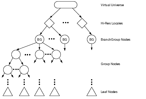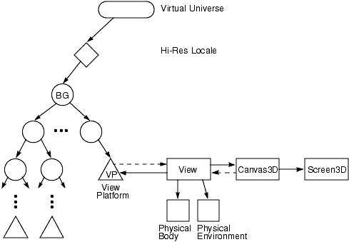
A scene graph consists of Java 3D objects, called nodes, arranged in a tree structure. The user creates one or more scene subgraphs and attaches them to a virtual universe. The individual connections between Java 3D nodes always represent a directed relationship: parent to child. Java 3D restricts scene graphs in one major way: Scene graphs may not contain cycles. Thus, a Java 3D scene graph is a directed acyclic graph (DAG). See Figure 1.
Java 3D refines the Node object class into two subclasses: Group and Leaf node objects. Group node objects group together one or more child nodes. A group node can point to zero or more children but can have only one parent. The SharedGroup node cannot have any parents (although it allows sharing portions of a scene graph, as described in "Reusing Scene Graphs"). Leaf node objects contain the actual definitions of shapes (geometry), lights, fog, sounds, and so forth. A leaf node has no children and only one parent. The semantics of the various group and leaf nodes are described in subsequent chapters.
A scene graph organizes and controls the rendering of its constituent objects. The Java 3D renderer draws a scene graph in a consistent way that allows for concurrence. The Java 3D renderer can draw one object independently of other objects. Java 3D can allow such independence because its scene graphs have a particular form and cannot share state among branches of a tree.
The hierarchy of the scene graph encourages a natural spatial grouping on the geometric objects found at the leaves of the graph. Internal nodes act to group their children together. A group node also defines a spatial bound that contains all the geometry defined by its descendants. Spatial grouping allows for efficient implementation of operations such as proximity detection, collision detection, view frustum culling, and occlusion culling.
A leaf node's state is defined by the nodes in a direct path between the scene graph's root and the leaf. Because a leaf's graphics context relies only on a linear path between the root and that node, the Java 3D renderer can decide to traverse the scene graph in whatever order it wishes. It can traverse the scene graph from left to right and top to bottom, in level order from right to left, or even in parallel. The only exceptions to this rule are spatially bounded attributes such as lights and fog.
This characteristic is in marked contrast to many older scene graph-based APIs (including PHIGS and SGI's Inventor) where, if a node above or to the left of a node changes the graphics state, the change affects the graphics state of all nodes below it or to its right.
The most common node object, along the path from the root to the leaf, that changes the graphics state is the TransformGroup object. The TransformGroup object can change the position, orientation, and scale of the objects below it.
Most graphics state attributes are set by a Shape3D leaf node through its constituent Appearance object, thus allowing parallel rendering. The Shape3D node also has a constituent Geometry object that specifies its geometry-this permits different shape objects to share common geometry without sharing material attributes (or vice versa).
The Java 3D renderer incorporates all graphics state changes made in a direct path from a scene graph root to a leaf object in the drawing of that leaf object. Java 3D provides this semantic for both retained and compiled-retained modes.
A Java 3D scene graph consists of a collection of Java 3D node objects connected in a tree structure. These node objects reference other scene graph objects called node component objects. All scene graph node and component objects are subclasses of a common SceneGraphObject class. The SceneGraphObject class is an abstract class that defines methods that are common among nodes and component objects.
Scene graph objects are constructed by creating a new instance of
the
desired class and are accessed and manipulated using the object's set
and get
methods. Once a scene graph object is created and connected to other
scene graph objects to form a subgraph, the entire subgraph can be
attached to a virtual universe---via a high-resolution Locale
object-making the object live. Prior to attaching a subgraph
to a virtual
universe, the entire subgraph can be compiled into an
optimized, internal format (see the
BranchGroup.compile()
method).
An important characteristic of all scene graph objects is that
they can
be accessed or modified only during the creation of a scene graph,
except where explicitly allowed. Access to most set and get
methods of objects that are part of a live or compiled scene graph is
restricted. Such restrictions provide the scene graph compiler with
usage information it can use in optimally compiling or rendering a
scene graph. Each object has a set of capability bits that enable
certain functionality when the object is live or compiled. By default,
all capability bits are disabled (cleared). Only those set
and get
methods corresponding to capability bits that are explicitly enabled
(set) prior to the object being compiled or made live are legal.
A Locale has no parent in the scene graph but is implicitly attached to a virtual universe when it is constructed. A Locale may reference an arbitrary number of BranchGroup nodes but has no explicit children.
The coordinates of all scene graph objects are relative to the HiResCoord of the Locale in which they are contained. Operations on a Locale include setting or getting the HiResCoord of the Locale, adding a subgraph, and removing a subgraph.
The View object is the central Java 3D object for coordinating all aspects of viewing. All viewing parameters in Java 3D are directly contained either within the View object or within objects pointed to by a View object. Java 3D supports multiple simultaneously active View objects, each of which can render to one or more canvases.
The PhysicalEnvironment object encapsulates all of the parameters
associated with the physical environment, such as calibration
information for the tracker base for the head or hand tracker.
