- java.lang.Object
-
- javafx.scene.Node
-
- javafx.scene.shape.Shape
-
- All Implemented Interfaces:
Styleable,EventTarget
- Direct Known Subclasses:
Arc,Circle,CubicCurve,Ellipse,Line,Path,Polygon,Polyline,QuadCurve,Rectangle,SVGPath,Text
public abstract class Shape
extends Node
TheShapeclass provides definitions of common properties for objects that represent some form of geometric shape. These properties include:- The
Paintto be applied to the fillable interior of the shape (seesetFill). - The
Paintto be applied to stroke the outline of the shape (seesetStroke). - The decorative properties of the stroke, including:
- The width of the border stroke.
- Whether the border is drawn as an exterior padding to the edges
of the shape, as an interior edging that follows the inside of the border,
or as a wide path that follows along the border straddling it equally
both inside and outside (see
StrokeType). - Decoration styles for the joins between path segments and the unclosed ends of paths.
- Dashing attributes.
An application should not extend the Shape class directly. Doing so may lead to an UnsupportedOperationException being thrown.
Interaction with coordinate systems
Most nodes tend to have only integer translations applied to them and quite often they are defined using integer coordinates as well. For this common case, fills of shapes with straight line edges tend to be crisp since they line up with the cracks between pixels that fall on integer device coordinates and thus tend to naturally cover entire pixels.On the other hand, stroking those same shapes can often lead to fuzzy outlines because the default stroking attributes specify both that the default stroke width is 1.0 coordinates which often maps to exactly 1 device pixel and also that the stroke should straddle the border of the shape, falling half on either side of the border. Since the borders in many common shapes tend to fall directly on integer coordinates and those integer coordinates often map precisely to integer device locations, the borders tend to result in 50% coverage over the pixel rows and columns on either side of the border of the shape rather than 100% coverage on one or the other. Thus, fills may typically be crisp, but strokes are often fuzzy.
Two common solutions to avoid these fuzzy outlines are to use wider strokes that cover more pixels completely - typically a stroke width of 2.0 will achieve this if there are no scale transforms in effect - or to specify either the
StrokeType.INSIDEorStrokeType.OUTSIDEstroke styles - which will bias the default single unit stroke onto one of the full pixel rows or columns just inside or outside the border of the shape.- Since:
- JavaFX 2.0
-
-
Property Summary
Properties Type Property Description ObjectProperty<Paint>fillDefines parameters to fill the interior of anShapeusing the settings of thePaintcontext.BooleanPropertysmoothDefines whether antialiasing hints are used or not for thisShape.DoublePropertystrokeDashOffsetDefines a distance specified in user coordinates that represents an offset into the dashing pattern.ObjectProperty<StrokeLineCap>strokeLineCapThe end cap style of thisShapeas one of the following values that define possible end cap styles:StrokeLineCap.BUTT,StrokeLineCap.ROUND, andStrokeLineCap.SQUARE.ObjectProperty<StrokeLineJoin>strokeLineJoinDefines the decoration applied where path segments meet.DoublePropertystrokeMiterLimitDefines the limit for theStrokeLineJoin.MITERline join style.ObjectProperty<Paint>strokeDefines parameters of a stroke that is drawn around the outline of aShapeusing the settings of the specifiedPaint.ObjectProperty<StrokeType>strokeTypeDefines the direction (inside, centered, or outside) that the strokeWidth is applied to the boundary of the shape.DoublePropertystrokeWidthDefines a square pen line width.-
Properties declared in class javafx.scene.Node
accessibleHelp, accessibleRoleDescription, accessibleRole, accessibleText, blendMode, boundsInLocal, boundsInParent, cacheHint, cache, clip, cursor, depthTest, disabled, disable, effectiveNodeOrientation, effect, eventDispatcher, focused, focusTraversable, hover, id, inputMethodRequests, layoutBounds, layoutX, layoutY, localToParentTransform, localToSceneTransform, managed, mouseTransparent, nodeOrientation, onContextMenuRequested, onDragDetected, onDragDone, onDragDropped, onDragEntered, onDragExited, onDragOver, onInputMethodTextChanged, onKeyPressed, onKeyReleased, onKeyTyped, onMouseClicked, onMouseDragEntered, onMouseDragExited, onMouseDragged, onMouseDragOver, onMouseDragReleased, onMouseEntered, onMouseExited, onMouseMoved, onMousePressed, onMouseReleased, onRotate, onRotationFinished, onRotationStarted, onScrollFinished, onScroll, onScrollStarted, onSwipeDown, onSwipeLeft, onSwipeRight, onSwipeUp, onTouchMoved, onTouchPressed, onTouchReleased, onTouchStationary, onZoomFinished, onZoom, onZoomStarted, opacity, parent, pickOnBounds, pressed, rotate, rotationAxis, scaleX, scaleY, scaleZ, scene, style, translateX, translateY, translateZ, viewOrder, visible
-
-
Field Summary
-
Fields declared in class javafx.scene.Node
BASELINE_OFFSET_SAME_AS_HEIGHT
-
-
Constructor Summary
Constructors Constructor Description Shape()Creates an empty instance of Shape.
-
Method Summary
All Methods Static Methods Instance Methods Concrete Methods Modifier and Type Method Description ObjectProperty<Paint>fillProperty()Defines parameters to fill the interior of anShapeusing the settings of thePaintcontext.static List<CssMetaData<? extends Styleable,?>>getClassCssMetaData()List<CssMetaData<? extends Styleable,?>>getCssMetaData()This method should delegate toNode.getClassCssMetaData()so that a Node's CssMetaData can be accessed without the need for reflection.PaintgetFill()Gets the value of the property fill.PaintgetStroke()Gets the value of the property stroke.ObservableList<Double>getStrokeDashArray()Defines the array representing the lengths of the dash segments.doublegetStrokeDashOffset()Gets the value of the property strokeDashOffset.StrokeLineCapgetStrokeLineCap()Gets the value of the property strokeLineCap.StrokeLineJoingetStrokeLineJoin()Gets the value of the property strokeLineJoin.doublegetStrokeMiterLimit()Gets the value of the property strokeMiterLimit.StrokeTypegetStrokeType()Gets the value of the property strokeType.doublegetStrokeWidth()Gets the value of the property strokeWidth.static Shapeintersect(Shape shape1, Shape shape2)Returns a newShapewhich is created as an intersection of the specified input shapes.booleanisSmooth()Gets the value of the property smooth.voidsetFill(Paint value)Sets the value of the property fill.voidsetSmooth(boolean value)Sets the value of the property smooth.voidsetStroke(Paint value)Sets the value of the property stroke.voidsetStrokeDashOffset(double value)Sets the value of the property strokeDashOffset.voidsetStrokeLineCap(StrokeLineCap value)Sets the value of the property strokeLineCap.voidsetStrokeLineJoin(StrokeLineJoin value)Sets the value of the property strokeLineJoin.voidsetStrokeMiterLimit(double value)Sets the value of the property strokeMiterLimit.voidsetStrokeType(StrokeType value)Sets the value of the property strokeType.voidsetStrokeWidth(double value)Sets the value of the property strokeWidth.BooleanPropertysmoothProperty()Defines whether antialiasing hints are used or not for thisShape.DoublePropertystrokeDashOffsetProperty()Defines a distance specified in user coordinates that represents an offset into the dashing pattern.ObjectProperty<StrokeLineCap>strokeLineCapProperty()The end cap style of thisShapeas one of the following values that define possible end cap styles:StrokeLineCap.BUTT,StrokeLineCap.ROUND, andStrokeLineCap.SQUARE.ObjectProperty<StrokeLineJoin>strokeLineJoinProperty()Defines the decoration applied where path segments meet.DoublePropertystrokeMiterLimitProperty()Defines the limit for theStrokeLineJoin.MITERline join style.ObjectProperty<Paint>strokeProperty()Defines parameters of a stroke that is drawn around the outline of aShapeusing the settings of the specifiedPaint.ObjectProperty<StrokeType>strokeTypeProperty()Defines the direction (inside, centered, or outside) that the strokeWidth is applied to the boundary of the shape.DoublePropertystrokeWidthProperty()Defines a square pen line width.static Shapesubtract(Shape shape1, Shape shape2)Returns a newShapewhich is created by subtracting the specified second shape from the first shape.static Shapeunion(Shape shape1, Shape shape2)Returns a newShapewhich is created as a union of the specified input shapes.-
Methods declared in class javafx.scene.Node
accessibleHelpProperty, accessibleRoleDescriptionProperty, accessibleRoleProperty, accessibleTextProperty, addEventFilter, addEventHandler, applyCss, autosize, blendModeProperty, boundsInLocalProperty, boundsInParentProperty, buildEventDispatchChain, cacheHintProperty, cacheProperty, clipProperty, computeAreaInScreen, contains, contains, cursorProperty, depthTestProperty, disabledProperty, disableProperty, effectiveNodeOrientationProperty, effectProperty, eventDispatcherProperty, executeAccessibleAction, fireEvent, focusedProperty, focusTraversableProperty, getAccessibleHelp, getAccessibleRole, getAccessibleRoleDescription, getAccessibleText, getBaselineOffset, getBlendMode, getBoundsInLocal, getBoundsInParent, getCacheHint, getClip, getContentBias, getCursor, getDepthTest, getEffect, getEffectiveNodeOrientation, getEventDispatcher, getId, getInitialCursor, getInitialFocusTraversable, getInputMethodRequests, getLayoutBounds, getLayoutX, getLayoutY, getLocalToParentTransform, getLocalToSceneTransform, getNodeOrientation, getOnContextMenuRequested, getOnDragDetected, getOnDragDone, getOnDragDropped, getOnDragEntered, getOnDragExited, getOnDragOver, getOnInputMethodTextChanged, getOnKeyPressed, getOnKeyReleased, getOnKeyTyped, getOnMouseClicked, getOnMouseDragEntered, getOnMouseDragExited, getOnMouseDragged, getOnMouseDragOver, getOnMouseDragReleased, getOnMouseEntered, getOnMouseExited, getOnMouseMoved, getOnMousePressed, getOnMouseReleased, getOnRotate, getOnRotationFinished, getOnRotationStarted, getOnScroll, getOnScrollFinished, getOnScrollStarted, getOnSwipeDown, getOnSwipeLeft, getOnSwipeRight, getOnSwipeUp, getOnTouchMoved, getOnTouchPressed, getOnTouchReleased, getOnTouchStationary, getOnZoom, getOnZoomFinished, getOnZoomStarted, getOpacity, getParent, getProperties, getPseudoClassStates, getRotate, getRotationAxis, getScaleX, getScaleY, getScaleZ, getScene, getStyle, getStyleableParent, getTransforms, getTranslateX, getTranslateY, getTranslateZ, getTypeSelector, getUserData, getViewOrder, hasProperties, hoverProperty, idProperty, inputMethodRequestsProperty, intersects, intersects, isCache, isDisable, isDisabled, isFocused, isFocusTraversable, isHover, isManaged, isMouseTransparent, isPickOnBounds, isPressed, isResizable, isVisible, layoutBoundsProperty, layoutXProperty, layoutYProperty, localToParent, localToParent, localToParent, localToParent, localToParent, localToParentTransformProperty, localToScene, localToScene, localToScene, localToScene, localToScene, localToScene, localToScene, localToScene, localToScene, localToScene, localToSceneTransformProperty, localToScreen, localToScreen, localToScreen, localToScreen, localToScreen, lookup, lookupAll, managedProperty, maxHeight, maxWidth, minHeight, minWidth, mouseTransparentProperty, nodeOrientationProperty, notifyAccessibleAttributeChanged, onContextMenuRequestedProperty, onDragDetectedProperty, onDragDoneProperty, onDragDroppedProperty, onDragEnteredProperty, onDragExitedProperty, onDragOverProperty, onInputMethodTextChangedProperty, onKeyPressedProperty, onKeyReleasedProperty, onKeyTypedProperty, onMouseClickedProperty, onMouseDragEnteredProperty, onMouseDragExitedProperty, onMouseDraggedProperty, onMouseDragOverProperty, onMouseDragReleasedProperty, onMouseEnteredProperty, onMouseExitedProperty, onMouseMovedProperty, onMousePressedProperty, onMouseReleasedProperty, onRotateProperty, onRotationFinishedProperty, onRotationStartedProperty, onScrollFinishedProperty, onScrollProperty, onScrollStartedProperty, onSwipeDownProperty, onSwipeLeftProperty, onSwipeRightProperty, onSwipeUpProperty, onTouchMovedProperty, onTouchPressedProperty, onTouchReleasedProperty, onTouchStationaryProperty, onZoomFinishedProperty, onZoomProperty, onZoomStartedProperty, opacityProperty, parentProperty, parentToLocal, parentToLocal, parentToLocal, parentToLocal, parentToLocal, pickOnBoundsProperty, prefHeight, prefWidth, pressedProperty, pseudoClassStateChanged, queryAccessibleAttribute, relocate, removeEventFilter, removeEventHandler, requestFocus, resize, resizeRelocate, rotateProperty, rotationAxisProperty, scaleXProperty, scaleYProperty, scaleZProperty, sceneProperty, sceneToLocal, sceneToLocal, sceneToLocal, sceneToLocal, sceneToLocal, sceneToLocal, sceneToLocal, sceneToLocal, screenToLocal, screenToLocal, screenToLocal, setAccessibleHelp, setAccessibleRole, setAccessibleRoleDescription, setAccessibleText, setBlendMode, setCache, setCacheHint, setClip, setCursor, setDepthTest, setDisable, setDisabled, setEffect, setEventDispatcher, setEventHandler, setFocused, setFocusTraversable, setHover, setId, setInputMethodRequests, setLayoutX, setLayoutY, setManaged, setMouseTransparent, setNodeOrientation, setOnContextMenuRequested, setOnDragDetected, setOnDragDone, setOnDragDropped, setOnDragEntered, setOnDragExited, setOnDragOver, setOnInputMethodTextChanged, setOnKeyPressed, setOnKeyReleased, setOnKeyTyped, setOnMouseClicked, setOnMouseDragEntered, setOnMouseDragExited, setOnMouseDragged, setOnMouseDragOver, setOnMouseDragReleased, setOnMouseEntered, setOnMouseExited, setOnMouseMoved, setOnMousePressed, setOnMouseReleased, setOnRotate, setOnRotationFinished, setOnRotationStarted, setOnScroll, setOnScrollFinished, setOnScrollStarted, setOnSwipeDown, setOnSwipeLeft, setOnSwipeRight, setOnSwipeUp, setOnTouchMoved, setOnTouchPressed, setOnTouchReleased, setOnTouchStationary, setOnZoom, setOnZoomFinished, setOnZoomStarted, setOpacity, setPickOnBounds, setPressed, setRotate, setRotationAxis, setScaleX, setScaleY, setScaleZ, setStyle, setTranslateX, setTranslateY, setTranslateZ, setUserData, setViewOrder, setVisible, snapshot, snapshot, startDragAndDrop, startFullDrag, styleProperty, toBack, toFront, toString, translateXProperty, translateYProperty, translateZProperty, usesMirroring, viewOrderProperty, visibleProperty
-
Methods declared in class java.lang.Object
clone, equals, finalize, getClass, hashCode, notify, notifyAll, wait, wait, wait
-
Methods declared in interface javafx.css.Styleable
getStyleableNode, getStyleClass
-
-
-
-
Property Detail
-
strokeType
public final ObjectProperty<StrokeType> strokeTypeProperty
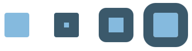
Defines the direction (inside, centered, or outside) that the strokeWidth is applied to the boundary of the shape.The image shows a shape without stroke and with a thick stroke applied inside, centered and outside.
- Default value:
- CENTERED
- See Also:
getStrokeType(),setStrokeType(StrokeType)
-
strokeWidth
public final DoubleProperty strokeWidthProperty
Defines a square pen line width. A value of 0.0 specifies a hairline stroke. A value of less than 0.0 will be treated as 0.0.- Default value:
- 1.0
- See Also:
getStrokeWidth(),setStrokeWidth(double)
-
strokeLineJoin
public final ObjectProperty<StrokeLineJoin> strokeLineJoinProperty
Defines the decoration applied where path segments meet. The value must have one of the following values:StrokeLineJoin.MITER,StrokeLineJoin.BEVEL, andStrokeLineJoin.ROUND. The image shows a shape using the values in the mentioned order.
- Default value:
- MITER
- See Also:
getStrokeLineJoin(),setStrokeLineJoin(StrokeLineJoin)
-
strokeLineCap
public final ObjectProperty<StrokeLineCap> strokeLineCapProperty
The end cap style of thisShapeas one of the following values that define possible end cap styles:StrokeLineCap.BUTT,StrokeLineCap.ROUND, andStrokeLineCap.SQUARE. The image shows a line using the values in the mentioned order.
- Default value:
- SQUARE
- See Also:
getStrokeLineCap(),setStrokeLineCap(StrokeLineCap)
-
strokeMiterLimit
public final DoubleProperty strokeMiterLimitProperty
Defines the limit for theStrokeLineJoin.MITERline join style. A value of less than 1.0 will be treated as 1.0.The image demonstrates the behavior. Miter length (
A) is computed as the distance of the most inside point to the most outside point of the joint, with the stroke width as a unit. If the miter length is bigger than the given miter limit, the miter is cut at the edge of the shape (B). For the situation in the image it means that the miter will be cut atBfor limit values less than4.65.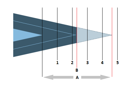
- Default value:
- 10.0
- See Also:
getStrokeMiterLimit(),setStrokeMiterLimit(double)
-
strokeDashOffset
public final DoubleProperty strokeDashOffsetProperty
Defines a distance specified in user coordinates that represents an offset into the dashing pattern. In other words, the dash phase defines the point in the dashing pattern that will correspond to the beginning of the stroke.The image shows a stroke with dash array
[25, 20, 5, 20]and a stroke with the same pattern and offset45which shifts the pattern about the length of the first dash segment and the following space.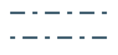
- Default value:
- 0
- See Also:
getStrokeDashOffset(),setStrokeDashOffset(double)
-
fill
public final ObjectProperty<Paint> fillProperty
Defines parameters to fill the interior of anShapeusing the settings of thePaintcontext. The default value isColor.BLACKfor all shapes except Line, Polyline, and Path. The default value isnullfor those shapes.- See Also:
getFill(),setFill(Paint)
-
stroke
public final ObjectProperty<Paint> strokeProperty
Defines parameters of a stroke that is drawn around the outline of aShapeusing the settings of the specifiedPaint. The default value isnullfor all shapes except Line, Polyline, and Path. The default value isColor.BLACKfor those shapes.- See Also:
getStroke(),setStroke(Paint)
-
smooth
public final BooleanProperty smoothProperty
Defines whether antialiasing hints are used or not for thisShape. If the value equals true the rendering hints are applied.- Default value:
- true
- See Also:
isSmooth(),setSmooth(boolean)
-
-
Method Detail
-
setStrokeType
public final void setStrokeType(StrokeType value)
Sets the value of the property strokeType.- Property description:
- Defines the direction (inside, centered, or outside) that the strokeWidth
is applied to the boundary of the shape.
The image shows a shape without stroke and with a thick stroke applied inside, centered and outside.
- Default value:
- CENTERED
-
getStrokeType
public final StrokeType getStrokeType()
Gets the value of the property strokeType.- Property description:
- Defines the direction (inside, centered, or outside) that the strokeWidth
is applied to the boundary of the shape.
The image shows a shape without stroke and with a thick stroke applied inside, centered and outside.
- Default value:
- CENTERED
-
strokeTypeProperty
public final ObjectProperty<StrokeType> strokeTypeProperty()
Defines the direction (inside, centered, or outside) that the strokeWidth is applied to the boundary of the shape.The image shows a shape without stroke and with a thick stroke applied inside, centered and outside.
- Default value:
- CENTERED
- See Also:
getStrokeType(),setStrokeType(StrokeType)
-
setStrokeWidth
public final void setStrokeWidth(double value)
Sets the value of the property strokeWidth.- Property description:
- Defines a square pen line width. A value of 0.0 specifies a hairline stroke. A value of less than 0.0 will be treated as 0.0.
- Default value:
- 1.0
-
getStrokeWidth
public final double getStrokeWidth()
Gets the value of the property strokeWidth.- Property description:
- Defines a square pen line width. A value of 0.0 specifies a hairline stroke. A value of less than 0.0 will be treated as 0.0.
- Default value:
- 1.0
-
strokeWidthProperty
public final DoubleProperty strokeWidthProperty()
Defines a square pen line width. A value of 0.0 specifies a hairline stroke. A value of less than 0.0 will be treated as 0.0.- Default value:
- 1.0
- See Also:
getStrokeWidth(),setStrokeWidth(double)
-
setStrokeLineJoin
public final void setStrokeLineJoin(StrokeLineJoin value)
Sets the value of the property strokeLineJoin.- Property description:
- Defines the decoration applied where path segments meet.
The value must have one of the following values:
StrokeLineJoin.MITER,StrokeLineJoin.BEVEL, andStrokeLineJoin.ROUND. The image shows a shape using the values in the mentioned order. - Default value:
- MITER
-
getStrokeLineJoin
public final StrokeLineJoin getStrokeLineJoin()
Gets the value of the property strokeLineJoin.- Property description:
- Defines the decoration applied where path segments meet.
The value must have one of the following values:
StrokeLineJoin.MITER,StrokeLineJoin.BEVEL, andStrokeLineJoin.ROUND. The image shows a shape using the values in the mentioned order. - Default value:
- MITER
-
strokeLineJoinProperty
public final ObjectProperty<StrokeLineJoin> strokeLineJoinProperty()
Defines the decoration applied where path segments meet. The value must have one of the following values:StrokeLineJoin.MITER,StrokeLineJoin.BEVEL, andStrokeLineJoin.ROUND. The image shows a shape using the values in the mentioned order. - Default value:
- MITER
- See Also:
getStrokeLineJoin(),setStrokeLineJoin(StrokeLineJoin)
-
setStrokeLineCap
public final void setStrokeLineCap(StrokeLineCap value)
Sets the value of the property strokeLineCap.- Property description:
- The end cap style of this
Shapeas one of the following values that define possible end cap styles:StrokeLineCap.BUTT,StrokeLineCap.ROUND, andStrokeLineCap.SQUARE. The image shows a line using the values in the mentioned order. - Default value:
- SQUARE
-
getStrokeLineCap
public final StrokeLineCap getStrokeLineCap()
Gets the value of the property strokeLineCap.- Property description:
- The end cap style of this
Shapeas one of the following values that define possible end cap styles:StrokeLineCap.BUTT,StrokeLineCap.ROUND, andStrokeLineCap.SQUARE. The image shows a line using the values in the mentioned order. - Default value:
- SQUARE
-
strokeLineCapProperty
public final ObjectProperty<StrokeLineCap> strokeLineCapProperty()
The end cap style of thisShapeas one of the following values that define possible end cap styles:StrokeLineCap.BUTT,StrokeLineCap.ROUND, andStrokeLineCap.SQUARE. The image shows a line using the values in the mentioned order. - Default value:
- SQUARE
- See Also:
getStrokeLineCap(),setStrokeLineCap(StrokeLineCap)
-
setStrokeMiterLimit
public final void setStrokeMiterLimit(double value)
Sets the value of the property strokeMiterLimit.- Property description:
- Defines the limit for the
StrokeLineJoin.MITERline join style. A value of less than 1.0 will be treated as 1.0.The image demonstrates the behavior. Miter length (
A) is computed as the distance of the most inside point to the most outside point of the joint, with the stroke width as a unit. If the miter length is bigger than the given miter limit, the miter is cut at the edge of the shape (B). For the situation in the image it means that the miter will be cut atBfor limit values less than4.65. - Default value:
- 10.0
-
getStrokeMiterLimit
public final double getStrokeMiterLimit()
Gets the value of the property strokeMiterLimit.- Property description:
- Defines the limit for the
StrokeLineJoin.MITERline join style. A value of less than 1.0 will be treated as 1.0.The image demonstrates the behavior. Miter length (
A) is computed as the distance of the most inside point to the most outside point of the joint, with the stroke width as a unit. If the miter length is bigger than the given miter limit, the miter is cut at the edge of the shape (B). For the situation in the image it means that the miter will be cut atBfor limit values less than4.65. - Default value:
- 10.0
-
strokeMiterLimitProperty
public final DoubleProperty strokeMiterLimitProperty()
Defines the limit for theStrokeLineJoin.MITERline join style. A value of less than 1.0 will be treated as 1.0.The image demonstrates the behavior. Miter length (
A) is computed as the distance of the most inside point to the most outside point of the joint, with the stroke width as a unit. If the miter length is bigger than the given miter limit, the miter is cut at the edge of the shape (B). For the situation in the image it means that the miter will be cut atBfor limit values less than4.65. - Default value:
- 10.0
- See Also:
getStrokeMiterLimit(),setStrokeMiterLimit(double)
-
setStrokeDashOffset
public final void setStrokeDashOffset(double value)
Sets the value of the property strokeDashOffset.- Property description:
- Defines a distance specified in user coordinates that represents
an offset into the dashing pattern. In other words, the dash phase
defines the point in the dashing pattern that will correspond
to the beginning of the stroke.
The image shows a stroke with dash array
[25, 20, 5, 20]and a stroke with the same pattern and offset45which shifts the pattern about the length of the first dash segment and the following space. - Default value:
- 0
-
getStrokeDashOffset
public final double getStrokeDashOffset()
Gets the value of the property strokeDashOffset.- Property description:
- Defines a distance specified in user coordinates that represents
an offset into the dashing pattern. In other words, the dash phase
defines the point in the dashing pattern that will correspond
to the beginning of the stroke.
The image shows a stroke with dash array
[25, 20, 5, 20]and a stroke with the same pattern and offset45which shifts the pattern about the length of the first dash segment and the following space. - Default value:
- 0
-
strokeDashOffsetProperty
public final DoubleProperty strokeDashOffsetProperty()
Defines a distance specified in user coordinates that represents an offset into the dashing pattern. In other words, the dash phase defines the point in the dashing pattern that will correspond to the beginning of the stroke.The image shows a stroke with dash array
[25, 20, 5, 20]and a stroke with the same pattern and offset45which shifts the pattern about the length of the first dash segment and the following space. - Default value:
- 0
- See Also:
getStrokeDashOffset(),setStrokeDashOffset(double)
-
getStrokeDashArray
public final ObservableList<Double> getStrokeDashArray()
Defines the array representing the lengths of the dash segments. Alternate entries in the array represent the user space lengths of the opaque and transparent segments of the dashes. As the pen moves along the outline of theShapeto be stroked, the user space distance that the pen travels is accumulated. The distance value is used to index into the dash array. The pen is opaque when its current cumulative distance maps to an even element of the dash array (counting from0) and transparent otherwise.An empty strokeDashArray indicates a solid line with no spaces. An odd length strokeDashArray behaves the same as an even length array constructed by implicitly repeating the indicated odd length array twice in succession (
[20, 5, 15]behaves as if it were[20, 5, 15, 20, 5, 15]).Note that each dash segment will be capped by the decoration specified by the current stroke line cap.
The image shows a shape with stroke dash array
[25, 20, 5, 20]and 3 different values for the stroke line cap:StrokeLineCap.BUTT,StrokeLineCap.SQUARE(the default), andStrokeLineCap.ROUND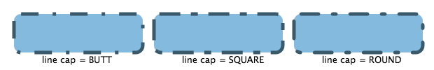
- Default value:
- empty
- Returns:
- the array representing the lengths of the dash segments
-
setFill
public final void setFill(Paint value)
Sets the value of the property fill.- Property description:
- Defines parameters to fill the interior of an
Shapeusing the settings of thePaintcontext. The default value isColor.BLACKfor all shapes except Line, Polyline, and Path. The default value isnullfor those shapes.
-
getFill
public final Paint getFill()
Gets the value of the property fill.- Property description:
- Defines parameters to fill the interior of an
Shapeusing the settings of thePaintcontext. The default value isColor.BLACKfor all shapes except Line, Polyline, and Path. The default value isnullfor those shapes.
-
fillProperty
public final ObjectProperty<Paint> fillProperty()
Defines parameters to fill the interior of anShapeusing the settings of thePaintcontext. The default value isColor.BLACKfor all shapes except Line, Polyline, and Path. The default value isnullfor those shapes.- See Also:
getFill(),setFill(Paint)
-
setStroke
public final void setStroke(Paint value)
Sets the value of the property stroke.- Property description:
- Defines parameters of a stroke that is drawn around the outline of
a
Shapeusing the settings of the specifiedPaint. The default value isnullfor all shapes except Line, Polyline, and Path. The default value isColor.BLACKfor those shapes.
-
getStroke
public final Paint getStroke()
Gets the value of the property stroke.- Property description:
- Defines parameters of a stroke that is drawn around the outline of
a
Shapeusing the settings of the specifiedPaint. The default value isnullfor all shapes except Line, Polyline, and Path. The default value isColor.BLACKfor those shapes.
-
strokeProperty
public final ObjectProperty<Paint> strokeProperty()
Defines parameters of a stroke that is drawn around the outline of aShapeusing the settings of the specifiedPaint. The default value isnullfor all shapes except Line, Polyline, and Path. The default value isColor.BLACKfor those shapes.- See Also:
getStroke(),setStroke(Paint)
-
setSmooth
public final void setSmooth(boolean value)
Sets the value of the property smooth.- Property description:
- Defines whether antialiasing hints are used or not for this
Shape. If the value equals true the rendering hints are applied. - Default value:
- true
-
isSmooth
public final boolean isSmooth()
Gets the value of the property smooth.- Property description:
- Defines whether antialiasing hints are used or not for this
Shape. If the value equals true the rendering hints are applied. - Default value:
- true
-
smoothProperty
public final BooleanProperty smoothProperty()
Defines whether antialiasing hints are used or not for thisShape. If the value equals true the rendering hints are applied.- Default value:
- true
- See Also:
isSmooth(),setSmooth(boolean)
-
getClassCssMetaData
public static List<CssMetaData<? extends Styleable,?>> getClassCssMetaData()
- Returns:
- The CssMetaData associated with this class, which may include the CssMetaData of its superclasses.
- Since:
- JavaFX 8.0
-
getCssMetaData
public List<CssMetaData<? extends Styleable,?>> getCssMetaData()
This method should delegate toNode.getClassCssMetaData()so that a Node's CssMetaData can be accessed without the need for reflection.- Specified by:
getCssMetaDatain interfaceStyleable- Overrides:
getCssMetaDatain classNode- Returns:
- The CssMetaData associated with this node, which may include the CssMetaData of its superclasses.
- Since:
- JavaFX 8.0
-
union
public static Shape union(Shape shape1, Shape shape2)
Returns a newShapewhich is created as a union of the specified input shapes.The operation works with geometric areas occupied by the input shapes. For a single
Shapesuch area includes the area occupied by the fill if the shape has a non-null fill and the area occupied by the stroke if the shape has a non-null stroke. So the area is empty for a shape withnullstroke andnullfill. The area of an input shape considered by the operation is independent on the type and configuration of the paint used for fill or stroke. Before the final operation the areas of the input shapes are transformed to the parent coordinate space of their respective topmost parent nodes.The resulting shape will include areas that were contained in any of the input shapes.
shape1 + shape2 = result +----------------+ +----------------+ +----------------+ |################| |################| |################| |############## | | ##############| |################| |############ | | ############| |################| |########## | | ##########| |################| |######## | | ########| |################| |###### | | ######| |###### ######| |#### | | ####| |#### ####| |## | | ##| |## ##| +----------------+ +----------------+ +----------------+- Parameters:
shape1- the first shapeshape2- the second shape- Returns:
- the created
Shape
-
subtract
public static Shape subtract(Shape shape1, Shape shape2)
Returns a newShapewhich is created by subtracting the specified second shape from the first shape.The operation works with geometric areas occupied by the input shapes. For a single
Shapesuch area includes the area occupied by the fill if the shape has a non-null fill and the area occupied by the stroke if the shape has a non-null stroke. So the area is empty for a shape withnullstroke andnullfill. The area of an input shape considered by the operation is independent on the type and configuration of the paint used for fill or stroke. Before the final operation the areas of the input shapes are transformed to the parent coordinate space of their respective topmost parent nodes.The resulting shape will include areas that were contained only in the first shape and not in the second shape.
shape1 - shape2 = result +----------------+ +----------------+ +----------------+ |################| |################| | | |############## | | ##############| |## | |############ | | ############| |#### | |########## | | ##########| |###### | |######## | | ########| |######## | |###### | | ######| |###### | |#### | | ####| |#### | |## | | ##| |## | +----------------+ +----------------+ +----------------+- Parameters:
shape1- the first shapeshape2- the second shape- Returns:
- the created
Shape
-
intersect
public static Shape intersect(Shape shape1, Shape shape2)
Returns a newShapewhich is created as an intersection of the specified input shapes.The operation works with geometric areas occupied by the input shapes. For a single
Shapesuch area includes the area occupied by the fill if the shape has a non-null fill and the area occupied by the stroke if the shape has a non-null stroke. So the area is empty for a shape withnullstroke andnullfill. The area of an input shape considered by the operation is independent on the type and configuration of the paint used for fill or stroke. Before the final operation the areas of the input shapes are transformed to the parent coordinate space of their respective topmost parent nodes.The resulting shape will include only areas that were contained in both of the input shapes.
shape1 + shape2 = result +----------------+ +----------------+ +----------------+ |################| |################| |################| |############## | | ##############| | ############ | |############ | | ############| | ######## | |########## | | ##########| | #### | |######## | | ########| | | |###### | | ######| | | |#### | | ####| | | |## | | ##| | | +----------------+ +----------------+ +----------------+- Parameters:
shape1- the first shapeshape2- the second shape- Returns:
- the created
Shape
-
-